
Institute for Telecommunication Sciences / About ITS / Resources / Table Mountain / History / Chapter 2: Ionospheric Telecommunications Laboratory
Chapter 2: Ionospheric Telecommunications Laboratory
|
|
|
|
|
|
|
|
|
|
|
|
|
|
The Ionospheric Telecommunications Laboratory provides technical information on radio propagation factors affecting design and use of radio systems. The emphasis of this work is on long-range radio transmission problems. Radio propagation studies are carried out for ionospheric, groundwave, and line-of-sight paths to define the limitations, disturbances, and capacity of the transmission medium as a channel. This information obtained is directed toward guidance of engineering practices, allocation and use of radio frequencies, and evaluation of system capabilities and limitations. Standards and methods of measurement are developed for radio systems to fulfill the needs of federal agencies and industry involved in radio telecommunications operation and regulation. Studies of information theory and coding, modulation, and antenna design are directed toward improvement of the reliability of systems and to the efficient utilization of the radio frequency spectrum. Consulting and advisory work is done in accordance with the needs of other government, commercial, and scientific agencies. A part of the experimental work required to render these services is done at the Table Mountain field site.
Small Turntable
Building B-9 houses measuring equipment and a modern antenna pattern recorder console which is synchro-linked to a small turntable located in the ground a short distance away from the roof of the building. Small model antennas are mounted on this turntable for radiation pattern measurements. It has also been used in an experimental aperture synthesis project. Across the road from B-9 is an erectable, 100-foot fiberglass tower used in measurements of full-size HF antennas as well as model antennas. It provides an approximate free-space environment for smaller antennas when they are mounted at, or near, its apex.
Large Turntable
The 34-foot diameter, steel turntable forms the roof of building T-4A. Beneath this unique roof is a large room housing the variable-speed rotating equipment, an antenna pattern recorder, and various pieces of associated equipment. The fiberglass tower, presently located near building B-9, can be mounted on this turntable for use in making radiation pattern measurements of full-size HF antennas at heights up to 100 feet. This is large turntable is currently being used in making radiation pattern measurements of model antenna arrays. When used for this purpose, the top of the turntable forms a large "perfectly conducting" ground plane under the model.
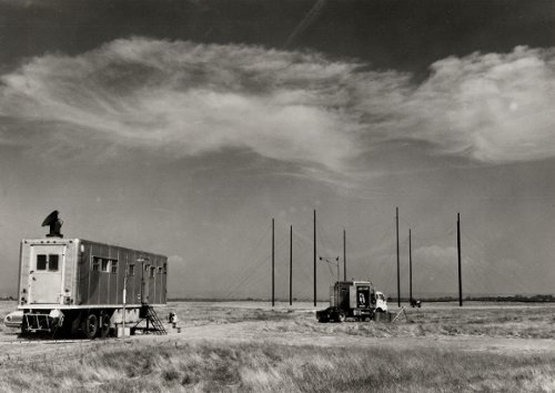
Mobile Antenna Measurement Trailer
Performance measurements of operational HF antennas can be made at various sites using the mobile laboratory located near Building B-9. This trailer-mounted laboratory contains the necessary equipment for the measurement of antenna impedance, gain, and power patterns. Data gathered in the field is recorded on magnetic type which is then computer-processed in the Boulder Laboratories. The equipment includes two 44.8-meter high mobile towers on which reference antennas are mounted, a 14-channel magnetic tape recorder for recording analog data, an auto-tracking radar to determine the position of the aircraft-mounted signal source, and eight channels of receiving-detecting equipment.
Measurements are made using up to five transmitters with antennas installed on an aircraft which is flown in nearly circular orbits at various ranges and altitudes to cover a nearly hemispherical surface about the antenna being tested. Aircraft position, together with eight data channels of received signals from the one or two antennas under test, are recorded simultaneously on the various channels of the analog tape recorder.
The magnetic tapes are digitized and fed into the digital computer along with correction factors for range and parallax. The computer output consists of a listing of all digitized points and a plot of constant power contours of azimuth versus elevation angle.
25-Element VHF Electronic Scanned Array
The VHF high resolution rapid-scan antenna consists of an array of 25 Yagi elements. The system operates on frequencies of 40.88 and 40.92 MHz. The beamwidth of the antenna is about two degrees and the scan rate is 20 Hz. This antenna is the prototype of the rapid-scan antenna used for the HF Radar project. The antenna has been used in propagation studies. Observations of signals from Long Branch, Illinois, showed that the received signal arrived by regular ionospheric scatter mode during the greater portion of the time. Occasionally, strong meteor-trail reflections exceeding the scattered signal by several orders of magnitude were observed and recorded. Signals propagated by sporadic-E layer have also been recorded. These signals, which usually arrive along the great circle path, are steady and high in amplitude.
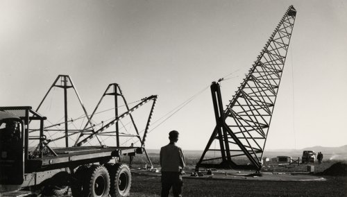
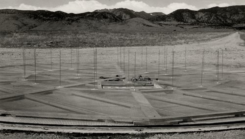
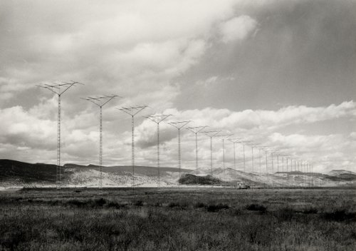
Back Scatter Radar Receiving Facility
The Table Mountain high frequency radar receiving facility is unique and has been designed for great flexibility in meeting the requirements of a multiplicity of measurement tasks in high frequency radar and high frequency propagation experiments in general.
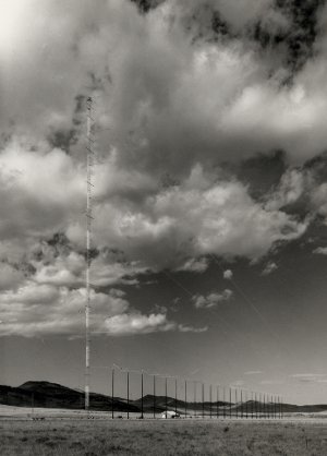
The essential elements of the facility consist of an elevation antenna array and an azimuth antenna array. The azimuth array is made up of 25 log periodic antennas mounted on the top of 80-foot poles. The elements of this array are equally spaced over a total aperture of 1392 feet. The elevation array consists of 10 log periodic antennas, of the same type used in the azimuth array, mounted on a 500-foot tower. These antennas were designed for a frequency range of 12-25 MHz. The beams formed have azimuthal beamwidths of 3° to 1.5° between the 12-25 MHz frequencies and elevation beamwidths of 6.5° to 3°. The beams can be steered over a sector width of 90° to 40° in the azimuth system and 52° to 21° in the case of the elevation system. The lower frequencies correspond to the larger sector.
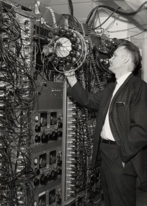
The beams are formed by the application of a local oscillator frequency to mechanically driven phase shifters. Because of mechanical limitations the beams may be scanned through the appropriate sector no faster than two scans per second. There are two independent beam formers for each array to provide greater capacity for making measurements.
Besides the beam forming electronics there are numerous equipments for programming, processing and recording data both on magnetic tape and by photographic techniques.
High frequency ground backscatter signals, direction of arrival information, signal phase variations, fading characteristics, and signal intensities can all be simultaneously measured with the system as it is constituted. Studies made or underway include those of signal focusing variations due to the irregular ionosphere, effective ground scattering coefficients, Doppler, fading, relative signal strength characteristics for different propagation paths, correlation of backscatter-indicated ionospheric irregularities with directional deviations of one-way signals, traveling ionospheric disturbances, high frequency band congestion as related to elevation angle of arrival, pulse compression techniques, cross array processing for pencil beam formation, and mapping of ionospheric parameters at a distance. This facility is one of the most flexible and versatile systems in the United States for use in the study of high frequency propagation and ionospheric radar systems problems.
Two-Element Short-Beverage Antenna Array
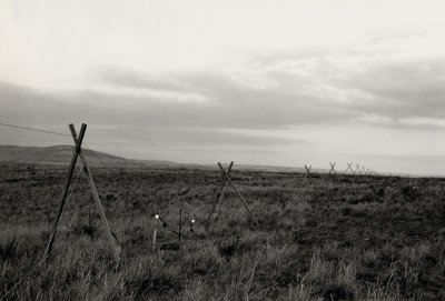
This array was constructed in order to fulfill a project requirement to evaluate a broadband directional antenna to be used for reception of signals in the ELF and VLF region. A two-element super-directive array using "Short Beverage" antennas as elements was selected as having the potential of fulfilling the requirements. Although the primary research in super-directive arrays at VLF has been done using small loops as elements, the prediction was that Beverage elements of length-to-wavelength ratio less than 0.1 could be substituted for the loops and the general pattern structure would be the same. The two-loop array theory predicts a front-to-back voltage ratio of 20 dB and half-power beamwidth of 75°. Advantages contemplated by using the Beverage elements were namely: (1) No transmission line or pre-amplifier requirements; (2) an entirely passive summing network with a consequently more stable antenna output; and (3) considerably higher signal level and possibly broader bandwidth.
A two-element Short-Beverage array has been constructed at Table Mountain and has an element length of 3700' or 1.125 km. It is supported approximately 4.5 feet above the ground. The experimental and theoretical data thus far compiled on the separate elements and the array confirm the prediction that the "Short-Beverage" array will generally assume the characteristic of an equivalently spaced loop array. It is also apparent that the "Short-Beverage" array is influenced by the wave velocity on the antenna lines and that the wave velocity is subject to values of soil conductivity and changes in soil conductivity due to surface moisture.
Continued theoretical and experimental investigation is planned for better understanding and utilization of the antenna characteristics.
Modulation Studies
Building F-6 houses two experimental projects in their initial stages. One of these deals with transportation communication research, the other is a project to develop an HF channel simulator. This location was also used recently to complete experimentation on HF digital errors.
Transportation Communication Research: One of the problems associated with a high-speed ground vehicle, such as a high-speed train, is communications. Typical communications required are command control, detection of obstructions, and determination of vehicle parameters such as speed, identification, and location. These data would ideally be communicated by a nonradiating process so as to introduce no additional congestion to the already over-crowded frequency spectrum and so that frequency allocations by the FCC would not be required.
One possible means of providing this form of communications is with a surface wave transmission line, or modifications thereof. In this regard, I.T.S.A. will provide the Office of High Speed Transportation the theoretical and experimental research required to determine the feasibility of utilizing a surface conduction line to satisfy the special requirements of the high-speed ground transportation problem. Some of the problems which will be investigated are: (1) the theoretical aspects of open and partially shielded surface waveguides; (2) determination of an optimum frequency; (3) determination of an optimum method of coupling between the line and mobile unit; and (4) determination of the line communications capacity.
HF Channel Simulator: The purpose of this project is to develop a high frequency channel simulator using a tapped-delay-line model with characteristics based upon propagation measurements. An experimental system is being developed for making both CW and pulse propagation measurements on the HF path from Long Branch, Illinois, to Boulder, Colorado. The required model tap delays will be obtained from the pulse measurements, and the CW measurements will be analyzed to determine the tap-gain modulation functions required at the delay-line tap outputs. Using these tap-gain functions, the resulting time-variant transfer characteristic of the model will be computed and compared with the corresponding measured characteristic. This will determine the accuracy with which the tapped-delay-line model can reproduce the characteristic of the propagation medium. The tap-gain functions will then be analyzed statistically and these results will be used to generate tap-gain functions with similar statistical characteristics. Using the synthesized tap-gain functions, the resulting response of the model will be computed, analyzed statistically, and these results compared with similar analyses of the measurements of the HF medium. The comparison will determine the statistical accuracy of the tapped-delay-line model. Based upon these results, an analog simulator will be designed and built.
HF Digital Errors: Building F-6 at Table Mountain has been used as the receiving site for an experimental high frequency communication circuit. The transmitting site is located at Long Branch, Illinois. The purpose of this experimental link was to study the relationship between propagation conditions and digital-error statistics. The digital information was transmitted using Frequency Shift Keying with rates ranging from 25 to 400 bits per second. The received sequence of binary bits was examined to determine which bits were in error. From this information various statistical distributions were determined (i.e., the distribution of the length of error-free sequences, the distribution of the length of consecutive bit errors, etc.).
The propagation parameters that were recorded are signal-to-noise ratio, multipath spread, and doppler spread. These propagation parameters are being correlated with the measured error distributions.
The results of this experimental program will be useful in the prediction of the performance of HF systems and in the design of error control techniques on HF circuits