Institute for Telecommunication Sciences / About ITS / 2022 / New Technical Report Describes Spectrum Measurements to Address EMC between Radar Altimeters and 5G
New Technical Report Describes Spectrum Measurements to Address EMC between Radar Altimeters and 5G
October 11, 2022
The introduction of Fifth Generation New Radio (5G NR) systems in the US between 3700 and 3980 MHz has raised concerns about electromagnetic compatibility with airborne radar altimeter (radalt) receivers operating between 4200 and 4400 MHz. NTIA Report TR-22-562, “Measurements of 5G New Radio Spectral and Spatial Power Emissions for Radar Altimeter Interference Analysis," documents an important step towards addressing these concerns.
The measurements described are part of a larger program by the Joint Interagency 5G Radar Altimeter Interference (JI-FRAI) Quick Reaction Testing (QRT) to understand potential 5G interference issues. JI-FRAI QRT was a Department of Defense led project that included technical participation from multiple federal agencies, cellular carriers, aerospace companies, airlines, related trade association groups, and academia. The data from this and three other test phases will be combined to reach an overall assessment of 5G and radalt compatibility. The ITS measurement data are available from the 5G_Aerial_RF_Radiation_Data repo at github.com/NTIA — DOI:10.5281/zenodo.7150540.
TR-22-562 describes two datasets and the measurement techniques used to collect them. The first dataset contains radiated wideband, wide dynamic range 5G base station emission spectra. The second dataset contains three-dimensional radiation patterns around 5G base station antennas. Four radio models produced by the three known manufacturers of C-band (3300–3980 MHz) 5G equipment deployed in the U.S. were measured. The emission spectrum measurements were performed with the Radio Spectrum Measurement System (RSMS)—a vehicle with specialized test equipment that lets ITS measure radiated base station emission spectra across a wide frequency range and with wide dynamic range.

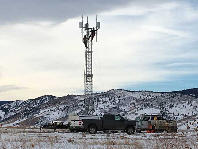
TR-22-562 Figure 34. One of the pair of Radio 1 CoWs at Table Mountain, with a set of three lower C band (3300–3600 MHz) MIMO panels at the “normal” 12 m (40 ft) height.
This report provides background information to help people understand 5G transmitters and radalt receivers. Topics include an introduction to the JI-FRAI QRT work program, the history of these radio spectrum bands, descriptions of radalts and 5G radio signals, and potential interference mechanisms. Two substantial stand-alone results are presented in this report:
- The measured, airborne EIRP data for the 5G MIMO arrays are consistent with numerical simulation data and manufacturers’ engineering specification sheets for the same, or similar, MIMO radiating arrays. This provides confidence in the use of radiation-pattern modeling for future 5G/radalt engineering studies in the C-band, offering the potential for considerable savings in time and cost.
- The measured emission spectra of the three high-band transmitters tested showed effective RF bandpass filtering, with cutoffs at 4 GHz, resulting in a low level of unwanted 5G emissions within the radalt band (4200-4400 GHz). This reduces the potential for a 5G-to-radalt harmful interference scenarios and increases the likelihood that unwanted emissions problems can be solved by installing or retrofitting radalt receivers with more-effective RF power-rejection filters.
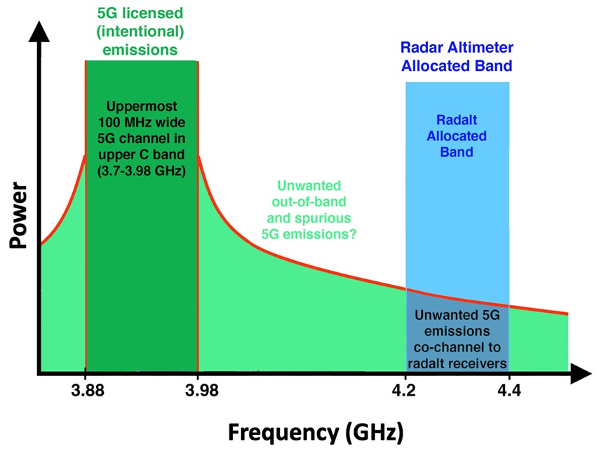
All 5G transmitters will produce some level of unwanted emissions within the radalt receiver’s band.

TR-22-562 Figure 25. Schematic representation of 5G unwanted emissions within the radalt receivers’ band.

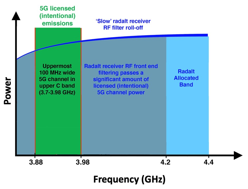
TR-22-562 Figure 26. Schematic representation of 5G desired (intentional) emissions producing harmful interference to radalt receivers due to insufficient radalt receiver RF filtering.
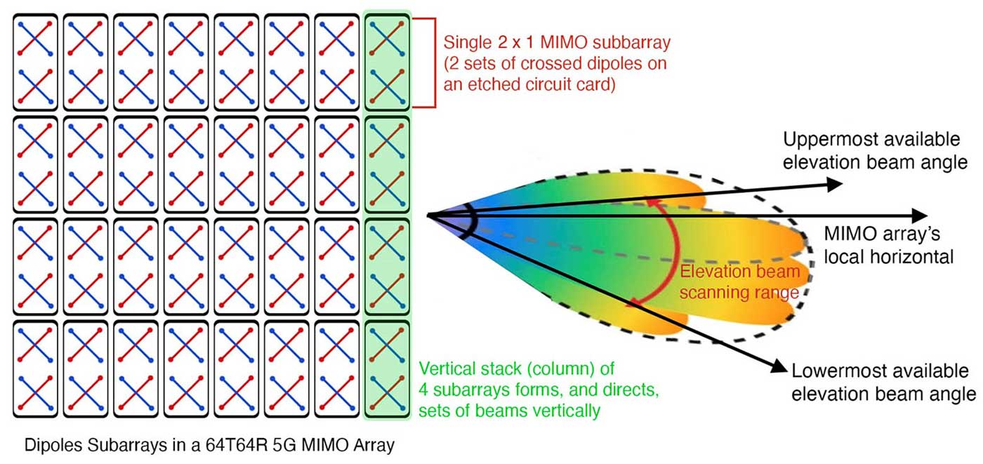
In addition, ITS measurements showed that 5G transmitters focus most of their emissions toward phones at ground level. Reception in high-rise buildings is more effectively accomplished with dedicated indoor wireless systems.

TR-22-562 Figure 17. Diagram of 64T64R MIMO array architecture and beam-directing capability.


